This article was originally published at ARM's website. It is reprinted here with the permission of ARM. For more information, please see ARM's developer site, which includes a variety of GPU Compute, OpenCL and RenderScript tutorials.
This is the first article of three that will focus on the implementation of Fast Fourier Transform (FFT) using the mixed-radix method on Mobile ARM® Mali™ GPU by means of OpenCL™.
This blog series continues the work of neiltan, who analyzed the main strategies for optimizing the radix-2 FFT algorithm in his blog Optimizing Fast Fourier Transformation on ARM Mali GPUs.
In this first post, we are going to build up a minimal background for the 1D complex to complex FFT algorithm by starting to point out the limits of DFT using the direct computation and exploiting the well-known and commonly used radix-2 FFT.
The mathematical prospective of FFT mixed-radix will be used to explain the key concepts of digit-reverse, twiddle factor multiplication and radix computation. These concepts will be covered more extensively in the second article, from the point of view of an implementation in OpenCL.
Before starting, we'd like to thank Georgios Pinitas and Moritz Pflanzer for their important help in reviewing this article and for their contribution to this implementation.
Discrete Fourier Transform
The Discrete Fourier Transform (DFT) is a domain transform (time -> frequency, image -> frequency,..) widely used in real-time digital signal processing for a variety of tasks such as spectrum analysis and convolution in the frequency domain.
It is defined as follows:

where:
- x(n) where n [0, N-1] is the n-th element of the input complex data sequence uniformly sampled
- X(k) where k [0, N-1] is the k-th element of the output complex DFT
The inverse function of the DFT, known as the Inverse Discrete Fourier Transform (IDFT), allows us to obtain the original function.

Commonly, the above expressions are written in the following tightly-packaged forms:


with


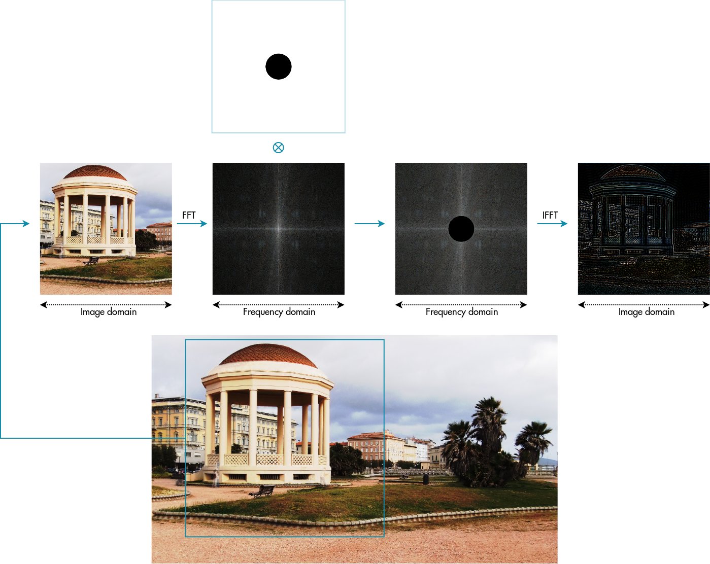
Convolution in the frequency domain corresponds to a simple pointwise multiplication
Analyzing the complexity of the direct computation of DFT
Generally the complexity of an algorithm can be defined in terms of a number of multiplications. We can easily infer the complexity of direct computation decomposing the N-point DFT in the real and imaginary parts:

where in the above relation we have applied the following trigonometric relation:

Equating the real and imaginary parts:


the direct computation would require:
- 2 trigonometric multiplications for N iterations for the real part = 2*N
- 2 trigonometric multiplications for N iterations for the imaginary part = 2*N
Since we have to compute K output complex values, we have:
- 2 * N * K for the real part
- 2 * N * K for the imaginary part
therefore the total multiplications are: 2*N^2 + 2*N^2 = 4 * N^2, declaring the complexity of direct computation as O(N^2).
Fast Fourier Transform – Cooley–Tukey algorithm
FFT is an efficient algorithm for producing exactly the same result (in the limit of precision) as DFT but with a complexity of O(N log2 N).
This method (and the general idea of FFT) was popularized by a publication of J. W. Cooley and J. W. Tukey in 1965, but it was later discovered that those two authors had independently re-invented an algorithm known to Carl Friedrich Gauss around 1805 (and subsequently rediscovered several times in limited forms).
https://en.wikipedia.org/wiki/Fast_Fourier_transform
The most famous and commonly used FFT algorithm is radix-2 Cooley–Tukey. It works just with N power of 2; behind this approach we find the "divide et impera" strategy which recursively breaks down the DFT into many smaller DFTs of size 2 called radix-2.
Essentially it is like we are seeing N composed by log2(N) 2's factors (i.e. N = 2 x 2 x..)

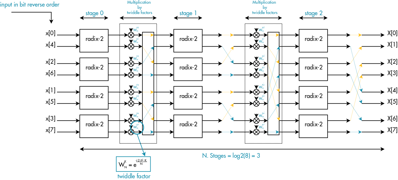
Looking at the above picture, we have:
- log2(N) radix-2 stages, each one composed of N/2 radix-2 basic elements
- (log2(N) – 1) twiddle factor multiplications stages
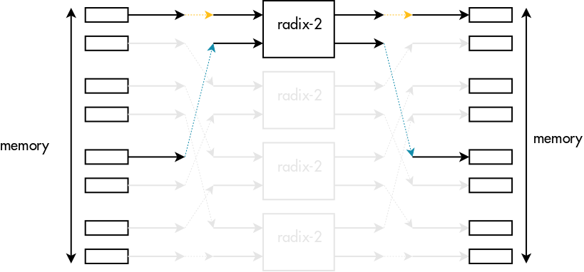
Please note that after the first radix stages, the inputs of each radix basic element will not be in consecutive order. In particular there will be an offset called "span" between each input, which will depend on the radix stage.
From radix-2 to mixed-radix
Often for signal processing applications, we design our system with radix-2 FFTs in mind. However, having N power of 2 for exact-fitting radix-2 FFTs can cause a significant performance drop in some applications.
For instance, if we consider the worst case for a 1D FFT, forcing the use of radix-2 would require double the amount of data input and consequently double the amount of computation. Moreover, this loss of performance would be much worse for the 2D case. In applications of image processing we have quite often dimensions not power of 2 and then doubling the size of both rows and columns, it would increase by a factor of 4 the total FFT size.
However, even if we have previously factorized N as N = 2 x 2 x 2…, any factorization would generally be possible.
Factorizing N as N = N1 x N2 x N3 x .. the "divide et impera" strategy remains the same but the new algorithm recursively breaks the DFT into many smaller DFTs of sizes N1, N2, N3 called respectively radix-N1, radix-N2, radix-N3,..
The generalization of the basic radix-2 FFT is called mixed-radix.
In terms of pipeline stages we are going to have:
- N / Ns DFTs of length Ns for each radix stage, where Ns is the radix order
- Z radix's stage with Z equal to the number of factors used for compounding the original length N.
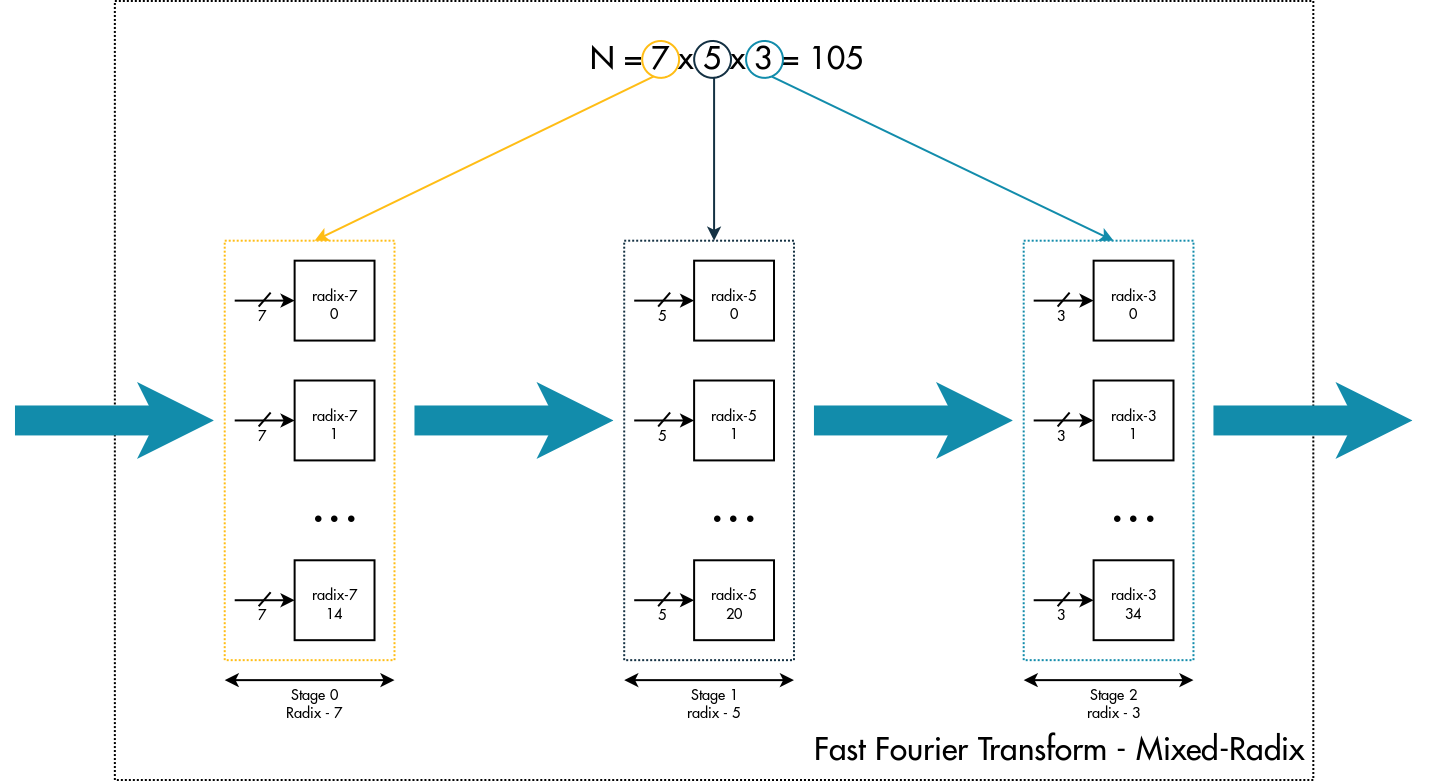
From this first analysis we can underline that the factorization is the fundamental principle behind the Cooley–Tukey algorithm and the radix-2 algorithm is just a special case of mixed radix.
Mixed-radix allows us to compute the FFT on any length N of input data. But, as typical implementations use a limited number of optimized radixes such as radix-2, radix-3, radix-5, radix-7, the computation will be restricted to those N that are an expansion of these available factors. In our case we are going to use:
- radix-2
- radix-3
- radix-4
- radix-5
- radix-7
so N must be compound of power of 2,3,5,7.

Please note: In the factorization of N there is not 4 as it is a power of 2. The motivation behind the choice to implement a highly optimized radix-4 will be clear in the second article, where we will compare the performance of radix-2 and mixed-radix algorithms.
Theory behind mixed-radix
This section will detail the math behind the Cooley-Turkey mixed-radix algorithm and will explain concepts such as twiddle factor multiplication and digit-reverse.
Since factorization is the key principle of Cooley–Tukey mixed-radix algorithm, let's start to decompose N in 2 factors, Nx and Ny:
![]()
Let's arrange the input data x(n) in a matrix with Nx columns and Ny rows where n-th element can be addressed in the following manner:

with:
- nx = n % Nx, scans the columns – nx [0, Nx – 1]
- ny = floor(n / Nx), scans the rows – ny [0, N / Nx – 1]
i.e. If we had N = 21 and we factorized N as N = 7 x 3, the 16-th element of the input array would be addressed:
- ny = floor(16 / 7) = 2
- nx = 16 % 7 = 2
address of 16-th element = 2 + 2 * 7
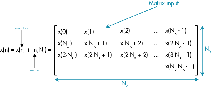
using this notation, the DFT can be written as follow:

Now let's place the output elements X(k) in a matrix as well, but with Nx rows and Ny columns. The motivation behind this choice will be clear during the demonstration.
The k-th element will be addressed with the following relation:

For addressing the output elements, we use kx and ky:
- kx = floor(k / Ny), scans the rows – kx [0, N / Ny – 1]
- ky = (k % Ny), scans the columns – ky [0, Ny – 1]
Addressing the output elements is completely upside down, because ky scans the columns while kx scans the rows.
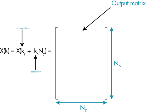
and the DFT becomes:

Let's evaluate the complex exponential:

- Term 1: Always 1 because it's a multiple of 2π
- -Term 4: A kind of trigonometric complex constant (twiddle factor)
The exponential is easy to study, thanks to choosing the output matrix with Nx rows and Ny columns.
Writing the 4th term as:

the final DFT's expression becomes:

This is the expression behind the computation of mixed-radix algorithm in the case of 2 factors.
If we had for instance N = 21 and we factorized N as N = 7 x 3, we could graphically summarize this final expression in the following manner:
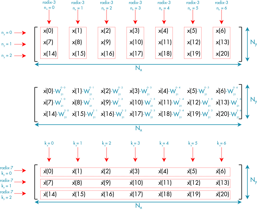
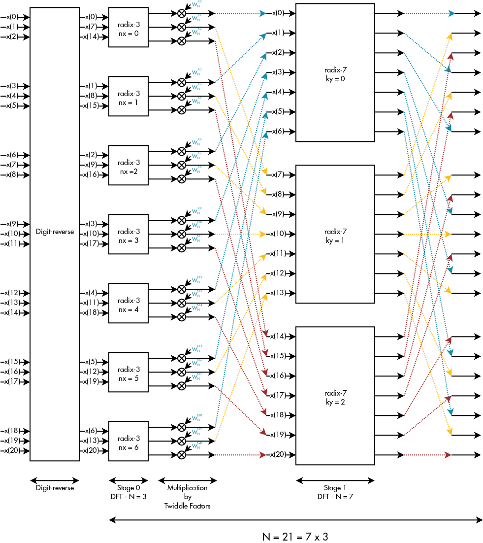
Which can be translated in the following pipeline:
Summary
- If Nx and Ny were composite numbers, we could again apply the decomposition to Nx and Ny
- The outer sum in the final expression is the DFT of each row after first multiplying by a proper trigonometric complex constant called the "twiddle factor"
- The final result does not change by swapping the order of the factors
- Looking at the picture above, we can easily guess that each stage of the pipeline is an embarrassingly parallel problem.
In the end from the demonstration we can highlight the 3 main computation blocks behind this algorithm:
- Digit-reverse stage, in order to have the output complex values in the correct order
- Twiddle factor multiplication stage, which multiplies each value by a proper complex constant before transmitting to the next radix stage
- Radix stage, which computes a highly optimized DFT
With this first article, we have illustrated the background behind the FFT mixed-radix algorithm, and we are now definitely ready to dive in the next article where we are going to play with OpenCL kernels.
Ciao,
Gian Marco Iodice
GPU Compute Software Engineer, ARM
References
- https://community.arm.com/groups/arm-mali-graphics/blog/2014/05/30/fast-fourier-transformation-vectorization-on-arm-mali-gpus
- http://www.engineeringproductivitytools.com/stuff/T0001/PT07.HTM
- Fast Fourier Transform – Algorithms and Applications, K. R. Rao, Do Nyeon Kim, Jae Jeong Hwang
- The Scientist and Engineer's Guide to Digital Signal Processing, Steven W. Smith

