This blog post was originally published at videantis' website. It is reprinted here with the permission of videantis.
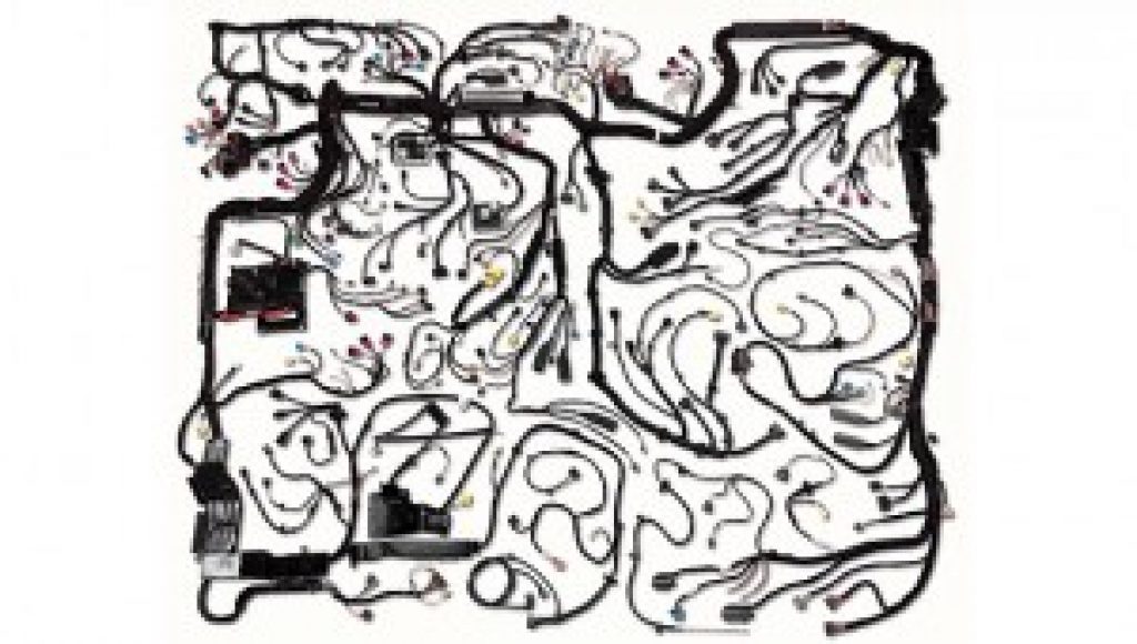
Several digital data communication standards are currently being used in the car: CAN, FlexRay, MOST, and LVDS. Each electronic component in the car typically uses its own dedicated wiring, making this cabling complex. The resulting wiring harness is very costly, with only the engine and chassis being more expensive. In addition, the wire harness is heavy and very labour-intensive to manufacture. Replacing traditional wiring with Automotive Ethernet has many advantages. A joint study by Broadcom and Bosch estimated that using “unshielded twisted pair cable to deliver data at a rate of 100 Mbps, along with smaller and more compact connectors can reduce connectivity cost up to 80 percent and cabling weight up to 30 percent.” The report Automotive Ethernet: An Overview by Ixia gives a good introduction and overview of the technology.
 One key application of using Ethernet in the car is to connect all the cameras to the head unit, displays, and other electronic control units in the car. There are many cameras in the car for rear view, surround view, mirror replacement, driver monitoring and front view. If you want to know more about what functions these cameras are performing, you can read a previous blog of ours. Most of these cameras today are connected by LVDS, which requires expensive shielded cabling and only provides point-to-point connections.
There are a few myths surrounding Ethernet and ADAS that are hurting adoption though. Here are three of them that we ran across.
Myth 1: Ethernet adds too much latency
LVDS sends over the pixels one at a time as they are read off of the image sensor, introducing very little delay. In contrast, Ethernet is much more complex: transmission requires video compression, going through the Ethernet stack, and decompression on the receiving side again. Each step adds latency, the delay between when the image was captured and when it is available for display or image analysis. But is it that bad really? Let’s go through these steps one by one.
Compressing the image data requires you to first buffer multiple lines before they can be compressed together. Video encoders typically compress 16-line macroblock rows at a time. With a video encoder that has been carefully optimized for low delay, this buffering adds only a few milliseconds for a typical 1.3Mpixel camera.
The next step is for the compressed bitstream data to go through Ethernet transmission: buffering, packetization, and sending it over the wire. In contrast to Ethernet used in PCs or servers, which is optimized for throughput, automotive Ethernet applications use a special variant of Ethernet (e.g. AVB or TSN) that is optimized for low delay and real-time applications. The result is that transmission over Ethernet also adds just a few milliseconds.
Finally, we have the decompression of the video stream on the other end of the wire again. The process is similar to the encoder, just in reverse, adding just a few milliseconds of delay.
In total, we see less than 10ms of delay in an Ethernet-based video transmission system. Putting this delay in context, at 30 frames per second, the time between the top line of an image and the bottom line is about 33ms, unless you use an expensive global shutter sensor. There’s much more delay in capturing an image than in the transmission of it. In 10ms a car at 180km/hr moves about half a meter. Delay does not seem to be an issue for automotive ADAS to adopt Ethernet.
Myth 2: Ethernet is too expensive, complexity raises cost of ICs
The hardware to support Ethernet in ICs is quite a bit more complex than what’s needed to support LVDS.
Ethernet is already price-competitive with LVDS when you take into account the higher cost of cabling of LVDS solutions. The additional video encoder and decoder add cost, but especially if you consider that the videantis codecs can be implemented without using DRAM, the cost adder is still minimal, and will go down further as more solutions are available. As a consumer, I can buy a 5-port Ethernet switch for much less than $10. The semiconductor content in such a switch is just a small fraction of the price. There’s no Moore’s law for cables, so as the volumes go up, Ethernet is an excellent solution to grab significant market share from the LVDS-based solutions with their expensive cables that are in use today.
In short, Ethernet provides a significant cost advantage, especially if you take into account the benefits at the system level.
Myth 3: Ethernet compresses the data and the resulting artifacts confuse the computer vision algorithms
An uncompressed 1.3Mpixel 4:2:0, 8-bit, 30fps video stream consumes 500 Mbps; this needs to be compressed by at least a factor of 5 in order to get below the 100 Mbps bandwidth that Ethernet supports. Lossless video compression techniques can’t guarantee such a compression ratio. Instead, lossy video compression techniques like Motion JPEG or H.264 must be used in order to transmit the video over Ethernet. Lossy video compression loses information and creates artifacts: the image that’s been transmitted over Ethernet is slightly different from the original image that was captured. These artifacts are exactly what computer vision algorithms developers are saying hinder their algorithms accuracy.
Noise is your enemy, not compression
Compression just adds noise to the signal. The original video signal goes in, and after compression/decompression a slightly different video signal comes out. This noise is not that different from the noise that the image sensor produces. In fact, the image sensor, especially in difficult lighting conditions, generates much more noise and distortion than a video codec. For instance, in low light there’s very little contrast and a lot of shot noise in the captured images. And in situations where there is a lot of light in some parts of the scene and very little light in others, for example at the end of a tunnel, the image sensor captures an image that’s quite distorted from the real scene. Making your computer vision algorithm robust to account for different lighting conditions is much harder than making it robust to lossy compression, especially at the high bitrate scenarios in 100 Mbps automotive Ethernet. For comparison, Full HD Blu-ray DVDs are compressed at a maximum of 50 Mbps, and the quality to the human eye of the compressed video is indiscernible from the original.
Developers should ensure their algorithms are robust to noise in general, putting the “video codec in the loop” when testing and validating their vision algorithms. The image data sets used for validation of the algorithms should include the noise and distortion added by both the image sensor and video transmission when the ADAS is deployed in the car. Noise is your enemy, not video compression artifacts.
Optimize the video encoder for computer vision
Most video codecs are optimized for consumer applications, where the final destination of the video is the human eye. Rear view, surround view and mirror replacement systems present captured images to the driver. At the same time, these cameras are becoming smart, and the captured images need to be analyzed by computer vision algorithms to understand the surroundings of the car to detect pedestrians, lanes, other cars, etc. These two targets actually have different requirements. While the human eye expects a high-resolution color image, computer vision algorithms often run on lower resolution images, work on monochrome image data, or analyze only parts of the captured image. If you take these differences into account, you can alter and optimize the video encoder specifically to accommodate for the computer vision algorithms happening downstream. Since our video coding solution is implemented in software, we enable such system-level optimizations, during the design of the camera, or even after assembly.
Put the computer vision in the camera, before compression
Another interesting solution is to put the computer vision algorithms inside the camera, operating on the original images before they are compressed for transmission over Ethernet. Cameras have stringent power consumption, size and cost requirements, but with a very efficient vision-processing platform this is possible. This approach provides additional significant advantages. Once the vision processing is in the camera, for example, the system becomes much more modular and plug-and-play.

Instead of overloading the central processing unit in a car when adding cameras, each camera adds compute power and can provide higher-level signals to the central processing unit, such as “pedestrian detected” or “moving object with velocity X and direction Y detected”. This way the standard car model doesn’t require a high-end central processing unit that can support ADAS options; instead, a lower-end, lower-cost central processing unit can be used. Driver monitoring solutions, smart rear view, front view, or mirror replacement cameras can then be offered as options that are self-contained, and a more powerful central processing unit is then no longer needed in every car.
Summary
All the techniques described here are complementary to each other and can be combined. Videantis provides a very low-power, high-performance unified computer vision processing and video-coding platform that can be tailored and optimized to the specific use case, in this case automotive Ethernet. Automotive ADAS and Ethernet are both high-growth markets, and we’ve shown there are different ways to debunk this myth that ADAS doesn’t work with automotive Ethernet-based systems.
Please don’t hesitate to reach out to us to discuss further or let us know your opinions on this matter.
Wireframe harness picture courtesy Delphi.
By Marco Jacobs
Vice President of Marketing, videantis


