This blog post was originally published at NVIDIA’s website. It is reprinted here with the permission of NVIDIA.
This post is the third in a series on building multi-camera tracking vision AI applications. We introduce the overall end-to-end workflow and fine-tuning process to enhance system accuracy in the first part and second part.
NVIDIA Metropolis is an application framework and set of developer tools that leverages AI for visual data analysis across industries. Its multi-camera tracking reference AI workflows, powered by cloud-native NVIDIA Metropolis microservices, enable advanced object tracking and localization across multiple cameras. This post discusses camera calibration, how to calibrate real cameras using the Metropolis Camera Calibration Toolkit, and how to calibrate synthetic cameras using the NVIDIA Omniverse extension.
Camera calibration
Camera calibration is the process of determining specific camera parameters or estimating the characteristics of a camera. Camera calibration enables translating what the camera sees in 2D into a real-world coordinate system and it is the foundation for many vision based applications. For example, camera calibration is needed to complete specific operations involving mainly coordinate conversions in creating a multi-camera tracking application.
Camera parameters are composed of two parts: extrinsic parameters and intrinsic parameters. Extrinsic parameters define the translation and rotation of the camera with respect to the designated world coordinate system, enabling a mapping between camera coordinates and the world coordinates. Intrinsic parameters enable mapping between camera coordinates and pixel coordinates.
Camera calibration in multi-camera tracking
NVIDIA Metropolis reference workflows for multi-camera AI primarily use cameras as sensors and extensively work with the spatial-temporal aspects of the detected moving objects. Objects are initially detected in the pixel domain within the camera view, and an essential step to enable many spatial-temporal analytics downstream is to correlate the pixel domain with a desired coordinate system.
Camera positioning has a significant impact on the overall accuracy of the downstream tasks in the Metropolis AI workflow. For details, see the Camera Positioning Guide. With proper camera calibration, it helps to locate the detected object in a desired coordinate system, This plays an essential role in many core abilities, including but not limited to:
- Location service using a camera as a sensor: Detect objects within the camera and compute their locations onto a coordinate system with real-world meaning through calibrated camera parameters. For example, a customer in a retail store seen from a camera can be located on the floor plan map.
- Activity correlation across multiple cameras: When multiple cameras are calibrated against the same coordinate system, you can correlate and reason across cameras to provide integrated insights. For example, the movement history in the shared coordinate system can help determine if person_A detected by camera_1, and person_B detected by camera_2 is the same person or not. A second example is seamlessly tracking one person walking in a warehouse that has different cameras covering separate sections.
- Distance-based metric computation: Due to the camera’s nature, the distance computation directly in the pixel domain is not reliable. For instance, the actual distance in meters covered by X number of pixels can vary significantly depending on the location within a frame. Calibrating a camera against a Cartesian coordinate system can make the distance computation handy.
Figure 1 shows an example of a real-time location system where the location of each individual person is tracked on the floor plan map of a 100,000 square-foot warehouse space covered by 100 cameras. Such a system builds upon the aforementioned core abilities enabled through proper camera calibration.
 Figure 1. A real-time location system tracking multiple objects across multiple cameras
The current Metropolis reference AI workflows assume that cameras have no or very little distortion. This ensures the mapping is linear between the pixel coordinate system and the designated world coordinate system. This is calculated with reference points selected from both coordinate systems.
In particular, a series of landmarks is required, where the pixel value (x, y) and world coordinates (X, Y, Z) are known for each of them. In many of our use cases, the designated world coordinate system is a 2D cartesian plane, or to be more concrete, an image of the floor plan map. Using a corner of the floor plan map as origin, this Cartesian can be translated as the pixel values of the plan map image.
In this sense, the world coordinates (X, Y, Z) become (X, Y), the 2D-to-3D mapping problem literally becomes a 2D-to-2D perspective transformation problem, and a 3 x 3 homography matrix computed from the landmarks as the output of this calibration process can be used to perform location transformation later.
Figure 2 provides two examples that demonstrate the process, considering the task is to find the mapping between the camera pixels on the left and the floor plan map on the right, the only thing needed is a series of landmarks {1, 2, 3, 4, …} that can be located on both the left and right. Once the series of landmarks is selected, camera location (x, y) and world location (X, Y) are then given as the corresponding pixel coordinates and the homography matrix can be easily calculated with existing libraries (OpenCV, for example).
 Figure 2. Reference points from both the camera view and the floor plan map
Now, solving the pixel-to-world mapping boils down to selecting the reference points and acquiring their pixel values in both the camera frame and floor plan map. This is not an easy task, as it may seem. A properly designed tool can drastically reduce the workload and simplify the task.
Simplifying real-world calibration with the Metropolis Camera Calibration Toolkit
With the Metropolis Camera Calibration Toolkit, you can perform camera calibration tasks and output files in the proper format to connect with other Metropolis services seamlessly.
Learn how to use the Metropolis Camera Calibration Toolkit
The Metropolis Camera Calibration Toolkit provides:
- Project organization, import, and export
- Easy camera import with Metropolis media services
- GUI for reference point selection
- On-the-fly reprojection error for self-checking
- Add-ons to support more Metropolis functionalities including regions of interest (ROIs) and tripwires
- File insertion using an API
Three calibrations modes are available:
- Cartesian Calibration: A method for creating an extrinsic calibration without a reference building map. As a user, you can create your global coordinate system.
- Multi-Camera Tracking: This mode is the most common way to use the Calibration Toolkit, and is the focus of this post. In this form, the user provides a building map, which each camera will calibrate to.
- Image: Draw tripwires and ROIs on an image and get the pixel coordinates. For some downstream tasks, certain artifacts need to be added to the camera view for computing a particular metric—object counting based on tripwire crossings, for example.
The easiest way to start is to use the assets provided in the sample apps to import a project. Given the calibration.json, the imageMetadata.json, and the Images.zip, a user can import a project that is already set up.
To create a Multi-Camera Tracking project from scratch, you’ll need a floor plan and a media service, or images from the cameras. Information from the cameras will be needed to help set the camera up for the Metropolis UI.
After you import a project or create a new one, the Project page will take you through the steps to create the necessary artifacts. To start, upload the floor plan. The floorplan can be a building map representative of the space the camera sees.
Next, if you’re using a media service, the sensors can be imported using the URL most relevant to the deployment case. This is the easiest way to get the sensors into the toolkit, but it’s not necessary. If you’re not using a media service, you’ll need to set up the sensors.
For each sensor, first create a new sensor and add the camera details. These details are necessary to import the camera into the Metropolis workflow. After closing the modal, you’ll see a sensor shown in the grid, where you can click the camera icon to upload an image. If you discovered sensors in the previous step, the images should have been pulled from the media service. Repeat this for each sensor.
When calibrating, create a polygon for each sensor on the camera image and its corresponding polygon on the floor plan. Choose points or landmarks in the floor plan space that are visible in the camera image. These corresponding pairs enable you to create a transformation matrix to map trajectories in the camera space onto the floor plan.
Ideally, select between eight and 15 points, depending on how large the space is. At least eight points are required to start. Figure 2 shows identified landmarks in the floorplan that are visible in the camera image. If the calibration seems to falter in one area, adding more points can help improve the trajectories.
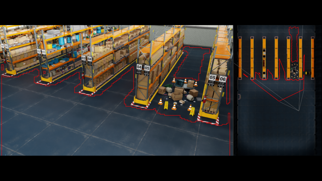
After creating the two polygons, add an ROI polygon, tripwires, and direction wires. See Figure 3 for an example of the calibration stage.
 Figure 3. An example of a fully calibrated camera after the Calibration stage in the Metropolis Camera Calibration Toolkit
After the calibration has been set up, click Calibrate to view the reprojection error and click accept (if acceptable). Then click Validate to test the calibration. Draw trajectories or polygons to see how points in the camera domain may fall on the floor plan. If the projected points on the floorplan are acceptable, you can Validate the calibration. If not, adjust the polygons in the calibration stage until the calibration is acceptable.
Next, set up the floor plan and place the camera on the floor plan map. This is necessary for the camera to appear in the UI of the Metropolis workflow. See Figure 4 for an example of how to place the sensor.
 Figure 4. A Sensor placed on the floor plan within the Metropolis Camera Calibration Toolkit
Finally, export the artifacts calibration.json, imageMetadata.json, and images.zip, which can be used in the Metropolis workflow.
With the Metropolis Camera Calibration Toolkit, you can easily streamline the workflow of manual camera calibration work on real cameras. It provides the formatted files for downstream Metropolis services to consume seamlessly.
Auto-calibration for synthetic cameras in NVIDIA Omniverse
Metropolis reference applications can work with synthetic data as well. The reference applications provide synthetic video data created within the NVIDIA Omniverse platform. Like real-world cameras, synthetic cameras must be calibrated to enable mapping between pixel coordinates and floor plan maps.
Get started with auto-camera calibration in NVIDIA Omniverse
With full control of the synthetic cameras in Omniverse, you don’t need to manually select reference points. Instead, the auto-calibration omni.replicator.agent.camera_calibration extension within Omniverse can output the desired mappings of virtual cameras with a click of a button. This auto-calibration calibration tool is included in the omni.replicator.agent extension. To learn more, see the Omniverse camera calibration documentation.
To use omni.replicator.agent.camera_calibration, first create a top-view camera, along with the cameras to be calibrated. The exact camera view from the top-view camera will be used as the floor-plan map. For each camera to be calibrated, the extension will auto-select points on the floor from the camera view and compute their correspondence in the top-view camera.
Details for using the omni.replicator.agent.camera_calibration extension are provided below:
- Reference points are automatically selected by casting rays randomly from the camera’s view, recording the positions where rays intersect with the floor.
- The camera’s extrinsic matrix is derived from the camera prim’s transform matrix, and the intrinsic matrix is computed using the properties of the camera prim.
- Convert the 3D positions of the reference points to 2D positions on the camera’s image plane and use this data to calculate the camera’s projection matrix.
- Compute the translation parameters and the scaling factor between the 3D positions of reference points and the top-view camera’s image plane. This provides the correspondence between the camera view and the floor plan map.
- Determine the camera’s field of view (FOV) by uniformly projecting rays to the ground, collecting data from the hits, and then generating the FOV polygon based on the coordinates of these hits.
- Finally, export the camera’s intrinsic and extrinsic matrices, along with the projection matrix and the correspondence between the camera view and the floor plan map, to a JSON file and render the FOV polygon on the scene’s top view image.
Creating synthetic cameras in Omniverse is relatively easy, and it is a great way to generate synthetic video data for various downstream tasks including model training and simulation. omni.replicator.agent.camera_calibration provides users with a handy tool to create formatted camera calibration files so that the synthetic cameras in Omniverse can be easily used in various Metropolis reference workflows or applications.
Conclusion
Camera calibration enables NVIDIA Metropolis reference applications to localize detected objects on a provided floor map and to spatially correlate object locations between multiple cameras. It is the essential step toward building large-scale, real-time location services and other meaningful services in the intelligent video analytics domain.
To learn more, see the following resources:
- Developer Guide on Multi-Camera AI workflows
- Real-Time Vision AI From Digital Twins to Cloud-Native Deployment with NVIDIA Metropolis Microservices and NVIDIA Isaac Sim
- Get Started with NVIDIA Metropolis Microservices
For technical questions, visit the NVIDIA Developer forums. Note that you must first sign up for the Developer Preview program.
Related resources
- DLI course: Building Real-Time Video AI Applications
- GTC session: Synchronize Multiple Sensors in Autonomous Machines
- GTC session: Leveraging Microservices for Building Complex and Large-Scale Vision AI Applications
- GTC session: Scaling Generative AI Features to Millions of Users Thanks to Inference Pipeline Optimizations
- SDK: DRIVE Constellation
- SDK: cuVSLAM
Dr. Shuo Wang
Senior System Software Engineer, Metropolis Team, NVIDIA
Arihant Jain
Senior Software Engineer, Metropolis Team, NVIDIA